Want to book by phone? Call usTel: +86 189 0119 4516 Email: overseas@hyliton.com
Email: overseas@hyliton.com Email: overseas@hyliton.com 


Beijing Hyliton Power Technology Co.,Ltd.
Address:6th floor of Tower B, Advanced Material Building, Yongfeng Industrial Base, Haidian Dist., Beijing, 100094 China.
Contact: Ms. Sarah Wang
Tel: +86 189 0119 4516
Mobile phone: +86 10 5871 1928 ext. 1759
Fax: +86 10 5871 1938
E-mail:overseas@hyliton.com

1 SummaryLine fault location and repair is the core of Distribution Grid (DG) Automation···

1 Summary
Line fault location and repair is the core of Distribution Grid (DG) Automation. Building a strong Smart DG to improve the DG Automation rate requires real and effective monitoring of the line, and analysis based on monitoring data. When the power line fails, it locates in time, displays the fault location, and guides the operation and maintenance personnel to quickly locate, then eliminate the fault and restore the power supply through various communication means, it providing guarantee and intelligent decision for the safe and stable operation of the power line.
Ø Atmospheric pressure:70kPa~106kPa
Ø Ambient temperature:Range of working ambient -40℃~+70℃; Maximum rate of change in ambient temperature:1℃/min
Ø Ambient humidity: the average relative humidity should not exceed 95% within 24h; the maximum absolute humidity is 25g/m2
Ø Salt mist concentration:5%
Ø Altitude:not exceed 2000m
Ø Line voltage:10KV
Ø Line current:0A~800A
Ø Applicable conductor section:16~400mm2
It is a set of smart fault and load management remote transmission system with function of distributed monitoring, centralized management and instant notification. It combines line fault detection, load monitoring and communication transmission technology, and sends information to the master system, then is sent to the relevant staff mobile phone via the master system. It makes the line fault point positioning and load real time monitoring become more quickly.
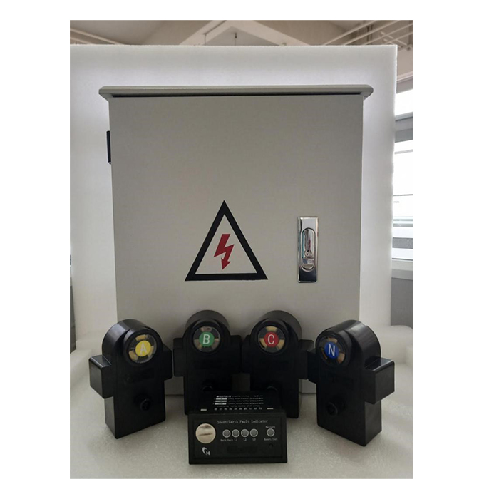
The panel of indicator is installed in Switchgear (or Ring Main Unit etc.),and display fault information locally.
Panel of indicator picture

Î Functions and features
Ä Short-circuit fault alarm indication: receive phase sequence acquisition unit information, and the indicator light indicates fault.
Ä Earthing fault alarm indication: receive zero sequence acquisition unit information, the indicator light indicates fault.
Ä Reset mode: manual reset; automatic reset of delay time can be set; remote reset.
Ä Power supply : lithium battery, rated 3.6V/2.4Ah
Î Technical parameters
Ä Working power supply: rated voltage 3.6V lithium battery (lifetime is not less than 8 years);
Ä Standby power current: ≤ 10μA;
Ä Automatic reset time:optional 4h/8h/12h/24h or according to customer's specific requirements. default:4h.
Ä Protection level: indicator IP40
Ä Output node capacity: DC30V, 2A
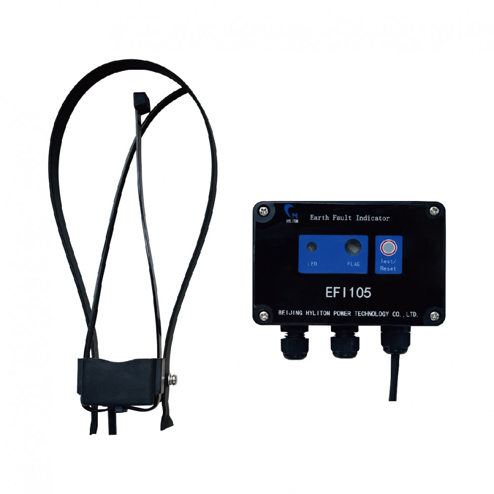
The acquisition units are installed on the cable line and are divided into phase sequence (A, B, C) acquisition units and zero sequence (N) acquisition unit for detecting the corresponding phase sequence and zero sequence cable. It can detect line information such as power transmission, power failure, earthing, short circuit, load current, etc., and transmit it via short-distance plastic optical fiber.
Acquisition unit picture

Î Functions and features
Ä Fault detection and alarm: short-circuit, earthing fault detection and alarm; it can distinguish permanent and transient faults.
Ä Analog monitoring: load current, product operation power monitoring
Ä Alarm mode: flash
Ä Communication: it communicate with the collection unit via short-distance plastic optical fiber
Ä Reset mode: manual reset; power-on reset; timing reset
Ä Parameter setting: set the action value remotely or locally, reset time and other parameters through the configuration tool.
Ä Anti-misoperation: It has the anit-misoperation alarm functions of load fluctuation, transformer no-load closing inrush current, line sudden load surge current, manual switching large load, non-fault phase reclosing flow, etc.
Ä Power supply: The CT line is powered and supplemented by a super capacitor as the main power source. The backup power supply is a non-rechargeable battery.
Ä Remote maintenance and upgrade (optional): remote configuration and maintenance upgrade
Ä Installation method: cable line power failure installation
Ä Anti-rust and anti-corrosion: long-term outdoor operation, the structure adopts anti-rust and anti-corrosion materials.
Î Technical parameter
Ä Short-circuit fault:
a) Short circuit fault action error ≤ ± 10%
b) Short circuit fault current minimum identification time ≤ 40ms
Ä Earthing fault:
a) Metal earthing recognition rate reaches 100%
b) Small resistance earthing recognition rate reaches 100%
c) Arc light earthing recognition rate reaches 90%
d) High-degree earthing (less than 800Ω) recognition rate reaches 90%
Ä Load current:
a) When load current is 0A~100A,measurement error is ±3A.
b) when it is 100A~600A,measurement error is ±3%.
Ä Automatically send a reset signal to the master station after reset:
Ä a) The permanent fault is automatically reset after power-on, and the power-on automatic reset time is less than 5min.
b) The timing reset time can be set, the setting range is less than 48h, the minimum resolution is 1min, and the timing reset time error is not more than ±1%
c) Perform remote reset of the master station.
Ä Flash interval: The flash signal is more than 50ms every time, the blinking period is 5s, and the visible distance at night is more than 300 meters.
Ä Optical fiber communication distance: ≤10m
Ä Static power consumption: ≤40μA
Ä Power:
a) Main power supply: When the line load current is greater than or equal to 10A, the CT takes power to meet the full-featured working requirements.
b) Backup power: super capacitor and non-rechargeable lithium battery as backup power.
Ä Weight:no more than 1kg
Ä Protection level:IP67
Ä Service life:no less than 8 years
The cable line collection unit is installed in the ring main units (RMU), switching station, and can be installed outdoors. It is an information forwarding device of the cable line online monitoring system, which is used for receiving information of the acquisition unit, and demodulating, decoding, re-encoding and transmitting to the working master station.
Collection unit picture

Î Function and features
Ä Communication with the acquisition unit: can receive multiple sets of acquisition unit information at the same time, and reply to confirmation
Ä Communication with the master station: communication with the master station via 4G wireless network
Ä Punctuality function: Receives the timing command and keeps the clock in sync with the system.
Ä Historical data storage: key historical information storage, query function
Ä Remote maintenance and upgrade: remote maintenance device, program upgrade
Ä Power supply: AC220V power supply or CT power supply, backup battery
Î Technical parameters
Ä Optical fiber communication distance: ≤10m
Ä Number of acquisition units: ≤12 groups (default is 6 groups)
Ä Remote communication: 4G communication method; communication protocol: IEC60870-5-101, IEC60870-5-104, etc.
Ä Backup battery specification: 12V, 7Ah, after the main power supply is lost, the device can work for one week.
Ä Static power consumption: ≤0.5W
Ä Mounting and fixing method: mounting ear or box mounting
Ä Protection level: IP55
Ä Size: 415mm × 325mm × 95mm
Ä Weight: ≤15kg
Ä Service life: 8 years
Ä The indicator can be installed on the front panel of the ring main unit(RMU) (distribution cabinet, cable branch box, etc.) with the hole size of 92*44 mm;
Ä Can make a special bracket to fix the indicator.
Ä Can be placed in the corner of the observable cabinet.
Ä The short-circuit acquisition unit is installed on the single-phase branch of the cable. The phase number of the installed cable is the same as the phase number of the acquisition unit. The metal hoop is used to fix the two parts of the acquisition unit on the cable branch so that it cannot fall off.
Ä When installing the earthing collection unit, be careful to enclose the three wires of the cable. The earthing wire of the cable must be worn back through the collection unit and fastened with a metal hoop to prevent slippage and fall off.
Ä Wall-mounted installation, hanging from the mounting ear by the mounting ear;
Ä The antenna for wireless communication of the collection unit needs to be pierced from the bottom of the cabinet to ensure that the signal will not be shielded. The antenna suction cup needs to be fixed in the place where it can be adsorbed.
Ä The antenna of the collection unit is led out through the hole at the bottom of the box away from the side of the door shaft;
Ä The earthing pin on the bottom of the collection unit needs to be grounded.
The “Panel Interface” on the acquisition unit needs to be connected to the corresponding phase interface of the panel of indicator:
Ä The “Panel Interface” of the A-phase acquisition unit needs to be connected to the L1 interface of the panel of indicator;
Ä The “Panel Interface” of the B-phase acquisition unit needs to be connected to the L2 interface of the panel of indicator;
Ä The “panel interface” of the C-phase acquisition unit needs to be connected to the L3 interface of the panel of indicator;
Ä The “panel interface” of the zero-sequence acquisition unit needs to be connected to the L0 interface of the panel of indicator.
The “Terminal Interface” on the collection unit needs to be connected to the corresponding phase interface of the collection unit:
Ä A-phase acquisition unit “terminal interface ”of Group N needs to be connected to the “NA” interface of the collection unit;
Ä B-phase acquisition unit “terminal interface ”of Group N needs to be connected to the “NB” interface of the collection unit;
Ä C-phase acquisition unit “terminal interface ”of Group N needs to be connected to the “NC” interface of the collection unit;
Ä Zero-sequence acquisition unit “terminal interface ”of Group N needs to be connected to the “NN” interface of the collection unit;
Ä The optical fiber cable of the collection unit is led out through the hole in the center of the bottom of the box.
Note: The first number N in NA, NB, NC, and NN represents a number from 1 to 12, depending on the configuration.
Ä The power supply cable uses 2.5 square millimeters;
Ä Connecting 110~220VAC from the corresponding terminal of the device;
Ä The power supply cable is led out from the hole on the side of the bottom of the collection unit.
Ä The bending radius of the fiber should be greater than 10cm;
Ä Avoiding the optical fiber to be pressed
Ä The optical fiber has four colors, yellow, green, red and black, which are used to connect to A, B, C and N respectively;
Ä After the fiber is inserted into the solid nut, tighten it to prevent it from falling off;
Ä When installing the earthing acquisition unit, pay attention to the earthing cable to go back to the acquisition unit line card.

Download the specifications of DYX-HY Cable Steady-state Remote Transmission Fault Indication System Transformers
Previous: no more
Next: no more

Copyright Beijing Hyliton Power Technology Co.,Ltd. All rights reserved.

Beijing Hyliton Power Technology Co.,Ltd.